Catenary Options
Ribbon: Home > Options
The Catenary dialog box is responsible for determining the specific catenary parameters and is split into several sections.
Material Constants for Contact Wires and Ropes
The Material Constants dialog box is used to determine the project-specific material data.

Enter the data and confirm with OK. In the following process of editing you can access those values.
Contact Wire Types
The Type of Catenary dialog box is used to determine the specific contact wire data. Set the name of the contact wire first.

After doing so, fill all fields with the suitable data. In the Material (reference) listbox, select the material that is valid for the contact wire you have entered in the Material Constants field. If it is not listed, choose Cancel and first enter the material data of the contact wire for all contact wires and ropes.
Messenger Wire and Stitch Wire Types
The Type of Rope dialog box is used to determine the specific rope data. Set the name of the rope type first.

After doing so, fill all fields with the appropriate data. In the Material (reference) listbox, select the material that is valid for this rope you have entered in the Material Constants field. If it is not available, you have to choose Cancel and first enter the material data of the messenger wire or stitch wire.
Catenary Data

The entries in the Catenary Data tab of the Catenary dialog are processed further in the catenary layout module. The type of contact wire and messenger wire must have been determined in their specific dialog boxes in order to select them at this point. Type of termination is the block name of the type of termination that is used in automatic positioning. Maximal number of supports per half type of termination and 1/2 tension length is the criterion for when a new type of termination should be included. In the Limiting Radius field, the minimum radius always has to be entered up to that for which this type of termination is valid.
Characterization of Catenary Height Reductions
The input fields for the relevant parameter by catenary height reduction are located in the Height Reduction Data tab.

To calculate the height reduction in the catenary layout module, a catenary must first be selected. Sicat Master uses the data of the height reduction dialog associated with the catenary.
Definition of Rules in the Span Length, Supports and Stitch Wire/Dropper Tabs
Rules for the planning are defined in the Span Length, Supports and Stitch Wire/Dropper tabs. The list for already existing rules is shown on the left half of the dialog. In the upper right range, the input parameter or conditions from the project are given for a rule. The input fields for the results or results parameter resulting from the input parameter are in the lower right range. For the creation of a new rule the button New must be activated, in the field Denomination a name for the rule must be assigned.
The parameter of the rule in the right range of the dialog can be adjusted now. Through changing the selection in the Listbox on the left side of the dialog the data are applied in the dialog and the data of the new selection are indicated at the same time. When closing the dialog all rules for the catenary type are transferred into the database.
The selected rule can be removed by clicking Delete.
Creation of Span Length Types
In the tab Span Lengths, you first have to enter a Span Length Designation and fill the fields with the specific technical data.
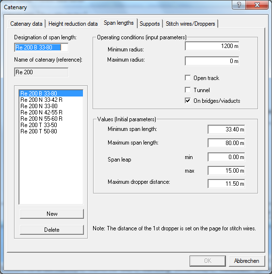
The following must be considered by the Minimum Radius till the Maximum Radius, and not by Opened Track, Tunnel or On Bridges/Viaducts:
The span length must be between the given minimum and maximum. The Span Length Different to the neighbour field must be between the indicated minimum and maximum. The Maximum Dropper Distance is not allowed to be greater than the given value.
Confirm the correctness and completeness of the data with OK. If you would like to assign several span lengths to the catenary that was created before, open that dialog several times and assign span length to the catenary layout type. This reference is indicated in the Name of Catenary (Reference) field. The span length created with the catenary reference is only valid for that catenary type.
Characterization of Support Points
In the Support Points tab, you first have to enter the Designation of Support and characterize the support point according to type, range of use and employment.

The following must be considered for all support points:
If the given conditions for a support are fulfilled in the upper range of the process data dialog in the catenary layout, it is allowed to have the maximum Given Stagger and a Radial Force between the minimum and maximum. If the support is created new, the given Contact Wire Height and System Height are allocated depending on the employment.
Continue filling the technical fields with data and confirm with OK. If you would like to assign several supports to the catenary that was created before, please open the dialog box several times and refer the supports to the catenary type. That reference is shown in the field Catenary name (reference). The support that has been created with a catenary reference is only valid for that special catenary type.
Characterization of Stitch Wire/Dropper
Denominations and rules in the Stitch Wires/ Droppers tab are adopted from the register support.
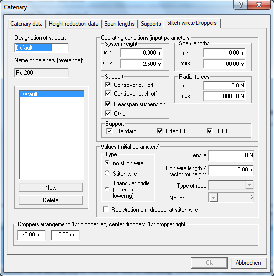
If no stitch wire is selected, the distance of the first dropper to both surrounding span length in the lower range of the dialogue must be set. If a stitch wire was selected, the number and arrangement of dropper must be set. The length and the type of rope for the stitch wire must be declared. The entry of the stitch wire tensile force and the registration arm dropper at stitch wire additionally has to be inserted at the stitch wire.